Your Cart is Empty


$1,800.00
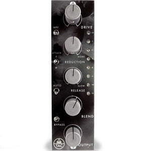
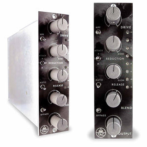
AwTAC Channel Compressor - 500 series FET compressor
Hand-build and wired in NYC, the AwTAC channel compressor for the 500 series format is a FET style compressor that sounds simply sublime. Some very cool features including the high pass filter and blend encoder, open up some very creative possibilities!
Type: 500 Series
-
-
AwTAC Channel Compressor PRODUCT FEATURES:
Drive Pot sets the level to the FET Controlled Amp in the compressor circuit. Below unity, the Drive Pot will raise the level fed to the compressor. Above unity, the Drive Pot will raise the level of distortion in the compressor. Since the sidechain will not distort the FET controlled amp, the Drive Pot is there to add distortion when desired.
HPF Switch engages a 6 dB/ Octave High Pass Filter to the side chain at 375 Hz. Seems like a high cut off point until you listen to it, the gradual slope allows your low end to breathe for a much more natural sounding vibe. Absolutely excellent on program material.
Reduction Pot controls the amount of compression applied to your input signal. Turn clockwise for more compression, fully counterclockwise for Off.
Attack Switch is a three position toggle switch which selects Fast (1.5 mS) in the up position, Medium (15 mS) in the down position and Slow (40 mS) in the middle position.
Release Pot sets the release time from 75 mS to 3.4 Seconds. Fastest setting is full counterclockwise.
Auto Switch engages an auto release circuit when the toggle is in the up position. When engaged, Release Pot orientation has no effect. The auto circuit is program dependent and very, very, smooth.Blend Pot is the fader for the Blend Amplifier which sets output level for the Parallel, uncompressed, circuit. Only the Parallel Blend signal is effected by this pot. Blend circuit provides +9dB of gain “in hand” similar to what is found on a proper console. Unity gain is denoted by the hash mark at 1 O’ Clock. Full Counter Clockwise mutes the Parallel Blend signal.
Output Potis the fader for the Make-up Amp which sets the output level for the Compression Circuit. Only the compressed signal is effected by this Pot.
Bypass Switch activates the relay controlled true bypass. In the up position, the compression and parallel blend circuits are engaged. In the down position the entire circuit AND transformers are bypassed at the edge connector: input signal comes in off the edge connector, through the relay and back out to the edge connector completely bypassing the Channel Compressor circuitry. When powered off, the unit defaults to “bypass” so signal will flow through with the rack off, no need to unpatch.
Meter is an 8 segment peak detecting LED meter which displays gain reduction only in the following steps: -0.5 dB, -1 dB, -2 dB, -3dB, -4 dB, -6 dB, -10dB, -15dB The meter is always on, even with the unit in bypass.
-
AwTAC Channel Compressor TECHNICAL SPECIFICATIONS:
Input Voltage Range:
+/-15 to 18VDC
Power Consumption:
+/-40mA
Size:
5.24″ x 1.49″ x 6.06″
Weight:
1lbCard Edge Connector
Pin 1 = Chassis (Earth)
Pin 2 = Output +
Pin 3 = N/A
Pin 4 = Output –
Pin 5 = Signal Common (Ground)
Pin 6 = DC Link
Pin 7 = Fader Loop Return
Pin 8 = Input –
Pin 9 = Fader Loop Send
Pin 10 = Input +
Pin 11 = N/A
Pin 12 = +VDC
Pin 13 = Signal Common (0VDC)
Pin 14 = -VDC
Pin 15 = N/ADrive Control
Unity gain (0 dB) at center (12 o’clock), with +7.8 dB fully clockwise and -9.6 dB fully counterclockwise, continuously variable
High Pass Filter (HPF) Control
Two-position toggle switch applies a first-order filter (6dB/octave) at approximately 375 Hz to the side chain signal when engaged (up)
Reduction Control
Level of signal sent to side chain, continuously variable from -infinity fully counterclockwise to unity gain fully clockwise
Compression Characteristic
Fixed attenuation followed by JFET-controlled variable amplification. Feedback design, peak-detecting, soft knee.
Compression Threshold
Varies according to position of DRIVE and REDUCTION controls. An incoming signal of approximately -24 dBu @ 1kHz is required for compression to begin (defined as -0.5 dB of gain reduction) when these controls are set to their fully clockwise (maximum) positions.
Compression Ratio
Varies from 1:1 to 20:1 according to signal level and threshold (soft knee). Nominally 10:1 when INPUT and REDUCTION controls set to their fully clockwise (maximum) positions.
Attack Control
Three-position toggle switch sets the side chain attack time
1.5mS (Fast) up
40mS (Slow) middle
15mS (Medium) downRelease Control
Release time continuously variable from 75mS fully counterclockwise to 3.4 Seconds fully clockwise
Auto Control
Two-position toggle switch defeats the release control and applies a program dependent release circuit when engaged (up)
Blend Control
Level of uncompressed signal continuously variable from -infinity fully counterclockwise to +9.3 dB fully clockwise, with unity gain (0 dB) at 1:30
Output Control
Level of compressed signal continuously variable from -infinity fully counterclockwise to +17.2 dB fully clockwise, with unity gain (0 dB) at 10:30
Bypass Control
Two-position toggle switch controls relay true bypass circuit, which selects between processed outgoing signal (up) and unprocessed incoming signal (down). Reverts to bypass (unprocessed) position when unit is powered off.
Gain Reduction Metering
Peak-detecting LED indication from -0.5 to -15 dB, in eight carefully selected steps. Displays real-time side chain voltage, regardless of bypass status.
Line Input
Nominally 10,000 Ω balanced bridging, transformer isolated
+4 dBu operating levelLine Output
Nominally 90 Ω balanced, transformer isolated
Max load 300 Ω or greater
+4 dBu operating levelTotal Gain
• +27 dB if DRIVE and OUTPUT controls both set fully clockwise, with REDUCTION and BLEND both set fully counterclockwise
Frequency Response (dBu) (Compressed Output)
+0/-1 35Hz to 12kHz
-6 @ 33.66kHz
-3 @ 23.18kHz
-3 @ 16 Hz
-6 @ 9 HzFrequency Response (dBu) (Blend Output)
+1/-1 10Hz to 20kHz
-6 @ 52kHz
-3 @ 44kHz
-0.3 @ 10HzPhase Shift (Compressed Output)
+102˚ @ 20kHz
+3˚ @ 1kHz
-45˚ @ 20HzPhase Shift (Blend Output)
+41˚ @ 20kHz
+1˚ @ 1kHz
-5˚ @ 20HzDistortion (THD+N at 0dBu unity gain through, Compressed Output)
No greater than 0.3% 20Hz to 20kHz
0.57% @ 80k
0.04% @ 31k5
0.13% @ 20k
0.55% @ 10k
0.03% @ 1k
0.06% @ 100Hz
0.3% @ 20Hz
0.48% @ 10HzDistortion (THD+N at 0dBu unity gain through, Blend Output)
No greater than 0.3% 20Hz to 20kHz
0.12% @ 80k
0.04% @ 31k5
0.03% @ 20k
0.03% @ 10k
0.03% @ 1k
0.08% @ 100Hz
0.26% @ 20Hz
0.52% @ 10HzMax Output for 1% THD+N @ 1kHz
Nominally +18 dBu (depending power supply voltages)
Max Input for 1% THD+N @ 1kHz
Greater than +30 dBu (if controls turned counterclockwise, or gain reduction active, to sufficiently prevent max output condition)
Noise (Compressed Output)
RMS 22 Hz to 22khz Unweighted = -78 dBu
RMS 400Hz to IEC-A Weighted = -79 dBu
Selectively Filtered (dBu) = -85 max @ 20kHz to -114 min @ 20Hz, with -95 nominal in the mid band (circa 1kHz)Noise (Blend Output)
RMS 22 Hz to 22khz Unweighted = -90 dBu
RMS 400Hz to IEC-A Weighted = -93 dBu
Selectively Filtered (dBu) = -96 max @ 20kHz to -122 min @ 20Hz, with -109 nominal in the mid band (circa 1kHz)Measurements taken from a randomly selected Channel Compressor module, installed in a Purple Audio Sweet Ten rack, using an Audio Precision Portable One Plus (GEN: 40Ω balanced floating, LOAD 20kΩ). Unless otherwise noted compressor signal path engaged, INPUT and OUTPUT controls set for unity gain, with all other controls at full counterclockwise, off, or resting positions. Specifications are subject to change without notice.
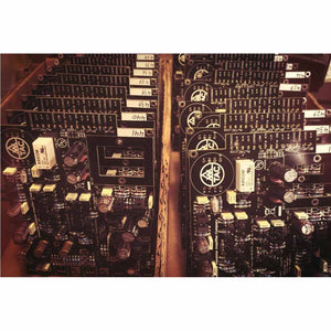
Each AwTAC Channel Compressor is assembled in Brooklyn, NY by a cheery staff of dedicated audio freaks, all of whom are full time NYC residents.
It’s 1970 design done right in 2014. And we are doing it with pride, in the USA. -
AwTAC Channel Compressor SYSTEM REQUIREMENTS:
Requires 500-series PSU chassis to operate. For more detailed technical specifications and information regarding the AwTAC Channel Compressor, please click the link below.